The kit, coming soon
Rather open one box than solder two dozen small wires?
I am putting together a kit: every part matched to the firmware, a printed case, and a board that arrives flashed and boot-tested. It is not open yet. It will be a threshold kit like my others: a refundable deposit to commit, and it only gets made if about 20 people commit. If it does not fill, every deposit comes back. The guide stays free either way.
Sign up for the newsletter and you will get an email the day it opens.
Get notified
Firmware updates, new add-ons, and the next build. Leave your email and you will hear about it first.
What it is
It is a wide 5.79 inch E Ink panel and a small ESP32-S3 board in a 3D printed case, with a d-pad on the back and a key at each end of the top edge. Speed read mode shows one, two or three words at a time in the same spot, so your eyes stop moving and you just read. It is also a normal page-by-page e-reader, and you send books to it from your phone or computer over WiFi.
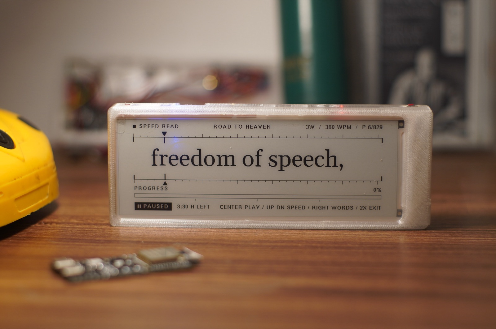
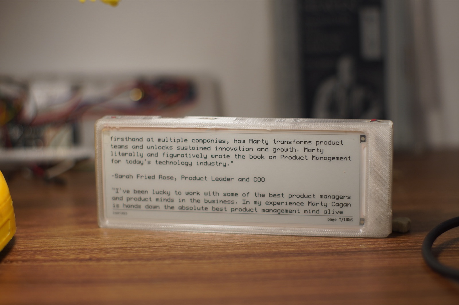
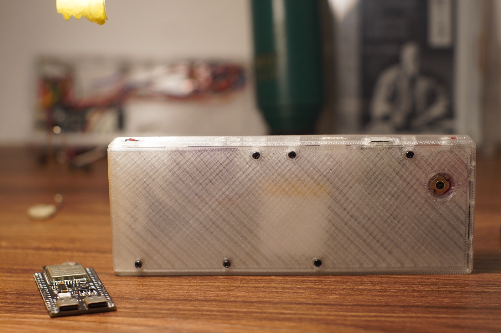
What the finished build does, core first, then the add-ons:
- Speed reader view. Words flash in place at the pace you set, from 100 words a minute up. Readable in sunlight, easy on the eyes.
- Books. A normal page view too, and it keeps your place in step with speed read. Send plain text books from your phone or computer over WiFi. No store, no account.
- Sequencer, coming soon (headphones add-on). A 4 track sequencer for chopping up samples, on the e-ink grid.
- Headphones. A small DAC board with a 3.5 mm jack on the top edge.
- Battery. A small rechargeable cell with a USB-C charger and a power switch.
- Open source. The firmware, the case files and this guide are free. Change anything you like.
This is a _stition build guide: everything here is free and open source. Questions while you build? Ask in #speed-reader on the _stition Discord. If you want to support the project, buy me a coffee on Ko-fi.
Is this build for you
Be honest with yourself here. This is the most fiddly build on this site. It is not hard to understand, but it is a lot of small, careful work.
- Soldering. You solder around twenty thin wires straight into the board's holes for the core alone (more for each add-on), with no header pins, because the case has no room for them. The two shoulder keys are bare 3 x 6 mm switches with tiny legs. If you have never soldered, build something simpler first, like the WiFi e-reader, then come back.
- Glass. The panel is a thin strip of glass and it cracks if it bends. One of mine cracked in transport inside an early case. Handle it by the edges and never flex it.
- Time. About 90 minutes for the core build in its case. The battery and the headphones add-ons take 45 to 60 minutes each. Count on about 3 hours for everything, once the parts and the printed case are on your desk.
- A printer. The case is a 3D print. No printer? A library, a maker space or an online print service can print it.
- No code needed. You flash ready-made firmware from the browser, in Chrome or Edge.
| Piece | Cost | What it adds |
|---|---|---|
| Core build | About $40 | The reader: panel, board, d-pad, two keys, case. Runs from USB. |
| Battery and charger | About $13 | Unplug it and take it with you. Most of it is the cell. |
| Headphones | About $6 | Wired audio, for the Sound test now and the sequencer soon. |
| Everything | About $60 | Most of it is the panel and the board. |
Per build. Most small parts come in packs, so your first build costs more (about $130 for everything, from Amazon and Good Display) and leaves spares for the next one.
Parts
Two parts matter: the board must be an ESP32-S3 N16R8 with two USB-C ports, and the panel must be the Good Display GDEY0579T93 with its DESPI-C579 adapter. The firmware is built for exactly that pair. Everything else has easy substitutes.
Order the panel and adapter together from Good Display, and everything else from Amazon. I bought my small parts in Vietnam, so the Amazon parts below are the closest matches to mine, not the exact listings I used; the notes say where they differ. Most come in packs, so your first build costs more than the per-build figures above and leaves spares. Put every Amazon part in your cart in one click (board, d-pad, keys, wire, charger, cell, switch, DAC, screws; remove the add-ons you do not want).
Core
| Part | What to buy | Price | Notes |
|---|---|---|---|
| Board | ESP32-S3 N16R8 dev board with two USB-C ports | $25 for 2 | N16R8 means 16 MB flash and 8 MB PSRAM. The firmware needs the 16 MB. |
| Panel + adapter | Good Display GDEY0579T93 with the DESPI-C579 adapter, 5.79 inch, 792 x 272, black and white. Part number GDEY0579T93 (spec page). | About $22 | A long thin bar of glass with a ribbon cable on one end, plus the small board its ribbon plugs into. Use the code stition3 at checkout. Not the GDEY0579Z93: that is the slow red and black version. |
| Adapter only | Good Display DESPI-C579 adapter board | About $6 | Only if you already have the panel. The bundle above includes it. |
| D-pad | 5-way tactile switch breakout, the small red board, about 23 x 21 mm | About $7 | Up, down, left, right and a center click, with pull-ups on the board. Pin labels vary by batch (mine reads + U C L D R −; others say COM, UP, DWN, LFT, RHT, MID): + or COM goes to 3V3. Not the bigger 25 x 41 mm "5D rocker" module with SET and RST buttons; it does not fit. |
| Keys | 2-pin SMD tact switches, 3 x 6 x 2.5 mm | About $7 for 100 | One at each end of the top edge. Optional for the reader, needed for the sequencer. |
| Wire | 30 AWG Kynar (wire-wrap) wire | About $7 a spool | Thin enough to fit the case: 0.8 mm across at most. A few colors make checking easier; thin silicone wire works too. |
| Capacitors (only if needed) | 470 uF electrolytic + 100 nF ceramic | under $1 | Mine runs fine without them. If the screen glitches, resets or comes up half drawn when it refreshes (a brownout), add them across the adapter's VCC and GND, as on my WiFi e-reader. |
| Screws | 6 x M2 x 5 self-tapping pan head screws | About $7 for 50 | Hold the back plate on. |
| Case | The printed case (files by email, see Case) | about 45 g of PETG, under $1 | Clear PETG on mine, something like this. |
| Cable | USB-C data cable | $0 if you have one | For flashing and for power. It must carry data, not just charge. |
Add-on: battery and charger
| Part | What to buy | Price | Notes |
|---|---|---|---|
| Charger | Type-C 5V 2A charge and boost board, "USB not welded" | About $10 for 6 | Charges the cell from USB and boosts it to a steady 5 V for the board. One part does both jobs. Buy the "not welded" version, with no USB-A socket fitted. Avoid boards sold as "5V 3.1A" (IP5310): three of them dropped my reader the moment it ran on battery. |
| Cell | LiPo pouch cell, 403035 size, 400 to 450 mAh, with its protection board | About $10 | 403035 means 4 x 30 x 35 mm, and that is the largest cell the case takes; a 503040 (600 mAh) is too big. Mine is 400 mAh; the Amazon one is 450. It comes with a small JST plug: cut it off and solder the leads, checking which is red (+) first, because plug wiring varies. Source your own; no cell ships in the kit. |
| Switch | MSK-12C02 SMD slide switch, 7 x 3 mm body | About $7 for 50 | Cuts all power. Sits in a pocket in the top edge. The bigger SS12D00G4 through-hole switch does not fit that pocket. |
Add-on: headphones
| Part | What to buy | Price | Notes |
|---|---|---|---|
| DAC | PCM5102A DAC board with a 3.5 mm jack (the purple GY-PCM5102) | About $12 for 2 | The jack comes out through the top edge of the case. |
| Headphones | Any wired headphones with a 3.5 mm plug | $0 if you have some | The case takes plugs up to 9 mm across. |
The Amazon links are affiliate links: if you buy through them, Amazon pays me a small cut at no extra cost to you. It funds the next guide. Good Display sponsors this guide; their links are plain links. Amazon prices move, so the prices here are rough.
Tools
- A soldering iron with a fine tip, and thin solder
- Wire strippers that handle 30 AWG wire, and flush cutters
- Tweezers, for the tiny key switches
- A multimeter with a continuity beep, for checking every wire before power goes on
- A hot glue gun, for the keys and loose wires in the case
- Tape, to hold the adapter board down inside the case
- A small Phillips screwdriver for the M2 screws
- A 3D printer, or someone who has one
- A USB-C data cable (a charge-only cable will not work for flashing)
- A computer with Chrome or Edge, for flashing
Pin map
Every wire in this build, core and add-ons, in one table. Each build step below points back here. The numbers are the GPIO numbers printed next to the board's pins. This table matches include/pins.h in the firmware, which is the source of truth if the two ever disagree.
| Part and pin | Board pin | Notes |
|---|---|---|
| Core: panel adapter (DESPI-C579) | ||
| BUSY | GPIO 1 | The adapter's header order BUSY, RES, D/C, CS, SCK, SDI runs 1, 2, 42, 41, 40, 39 on the board, so the six wires do not cross. |
| RES | GPIO 2 | |
| D/C | GPIO 42 | |
| CS | GPIO 41 | |
| SCK | GPIO 40 | |
| SDI | GPIO 39 | |
| VCC | 3V3 | 3.3 V, never 5 V. |
| GND | GND | The GND pin in the corner beside TX. |
| Core: d-pad module | ||
| + | 3V3 | Must be connected. Left open, the module ghosts presses across lines. |
| − | GND | |
| R | GPIO 10 | Wired by the labels on the module. The module sits upside down on the back of the case and the firmware turns the directions around for you. |
| D | GPIO 11 | |
| L | GPIO 12 | |
| C | GPIO 13 | |
| U | GPIO 14 | |
| Core: shoulder keys (each key: one leg to its pin, the other to GND) | ||
| K1 (left end) | GPIO 9 | Left and right as seen from the front. K2 sits on strapping pin 46: never hold it while the board powers up or resets. |
| K2 (right end) | GPIO 46 | |
| Add-on: headphones (PCM5102A DAC board, in its header order) | ||
| VIN | 3V3 | Not 5V: the board's 5V pin is an input only. |
| GND | GND | |
| LCK | GPIO 4 | Word select |
| DIN | GPIO 5 | Audio data |
| BCK | GPIO 6 | Bit clock |
| SCK | GND | Tie it to ground. It is not a board pin. |
| Add-on: battery and charger | ||
| Charger out + | Slide switch, then the board's 5V pin | Never plug the board's own USB in with the switch on. |
| Charger out − | GND | |
| Cell red / black | Charger BAT + / BAT − | Check twice before you solder. |
| Leave empty | ||
| GPIO 0, 45 | nothing | Strapping pins. |
| GPIO 19, 20 | nothing | The board's own USB. |
| GPIO 7, 8, 15 to 18, 38 | spare | GPIO 3 is free too, but it is a strapping pin. |
The board has several GND pins and two 3V3 pins. Any of them will do. Wires can share a pin if you join them.
Build the core
The core is a complete reader on its own. You can build it on the bench first, flash it, read a book on it, and only then put it in the case. Every wire goes by the pin map.
Plug the panel into the adapter
Lay the panel face down on something soft and flat. Open the latch on the adapter's ribbon socket, slide the ribbon in with its contacts facing the socket's contacts, and close the latch. In the case the ribbon folds 180 degrees back under the glass into the adapter, so leave it room to curve; never crease it. The DESPI-C579 has no switches to set; the gold pads on it (GDR, RESE, VCOM and the rest) are test points, so leave them alone.
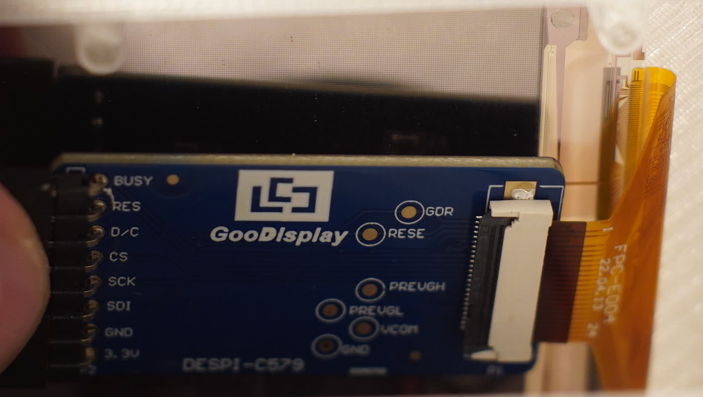
CheckYou should see the ribbon sitting straight and fully in the socket, with the latch closed flat over it.
Wire the adapter to the board
Eight wires: BUSY, RES, D/C, CS, SCK and SDI to GPIO 1, 2, 42, 41, 40 and 39, then VCC to 3V3 and GND to the GND pin beside TX. The adapter's header order matches a straight run of board pins, so the wires do not cross.
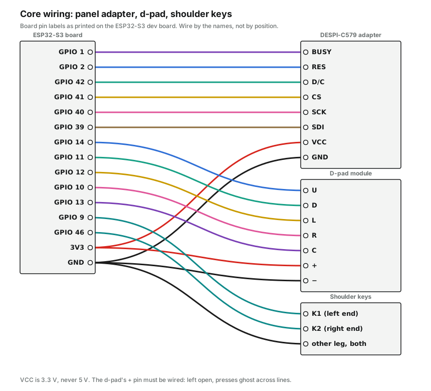
CheckYou should hear the multimeter beep between each adapter pin and its board pin, and stay silent between any two neighbouring pins.
Wire the d-pad
Seven wires, by the labels printed on the module: R to GPIO 10, D to 11, L to 12, C to 13, U to 14, − to GND and + to 3V3. Do not skip the + wire. Without it the module ghosts, and one press shows up on the wrong line. In the case the module sits upside down on the back plate and you press it from behind; the firmware already turns the directions around for that, so wire it by the labels and do not swap anything.
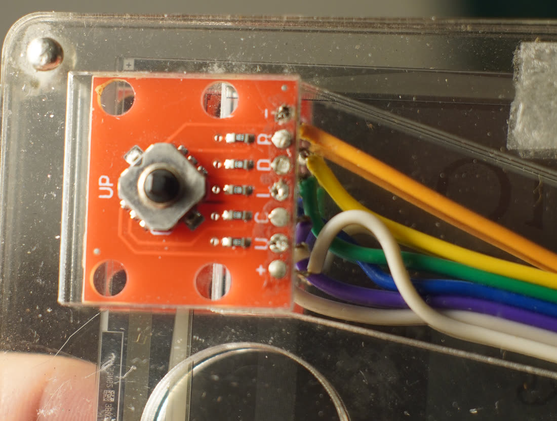
CheckYou should hear a beep between each signal pad and its board pin, and no beep between any two signal pads while nothing is pressed.
Wire the two shoulder keys
Each key is a bare 3 x 6 mm switch with two legs on each short side. One side goes to GND, the other to its board pin: K1 (the left end, as you look at the front of the reader) to GPIO 9, K2 (the right end) to GPIO 46. The keys sit at opposite ends of the case, so each gets its own GND wire, or one long GND wire run along the top wall. If you are building the case, glue the keys into their pockets first and wire them in place; see Case. The keys are optional for the reader (each one doubles a d-pad direction), but the sequencer will need K2.
K2 is on a strapping pin, which the board reads at the moment it powers up to decide how to boot. Held down at that moment, it can stop the reader from starting. Just do not hold it while you plug in or press reset.
CheckYou should hear a beep between each key's signal wire and GND only while you press that key, and silence when you let go.
Before you power it
Look over every joint with a bright light. Check for stray strands of wire touching the next pad, and for any wire on 5V (nothing in the core goes there).
CheckYou should hear no beep between 3V3 and GND on the board. A beep there means a short: find it before you plug in.
Flash it
Flash the core now, before you add anything else. The reader firmware runs with any of the add-ons missing: no battery, no DAC, no keys. That way you know the core works before you add more wires. The firmware is open source at github.com/AllanBinder/ereader. It is the same firmware as my WiFi e-reader, built for this panel and pin map.
Or from source. If you want to change the firmware, install PlatformIO, clone the repo, and from its folder run:
pio run -e esp32s3_579_fast -t upload     # the firmware
pio run -e esp32s3_579_fast -t uploadfs   # the book storage, once, on a fresh board
A fresh board needs the second command once. Without it there are no books and nowhere to upload them. Run it again later and it wipes your books, so only do it the first time. If the upload says "No serial data received", unplug, hold BOOT, plug back in, let go and try again. After flashing, tap RST to start the reader.
- First screen. The reader starts on the wide panel and shows its menu. It comes with one book already on it, Alice's Adventures in Wonderland (public domain), so you can try speed read straight away.
- Connect it to WiFi. In the menu, pick WiFi and settings, then WiFi setup. The reader puts up a network called
ereader-setup. Join it from your phone, pick your home network, type the password. - Add books. Under WiFi and settings, pick Books and games (WiFi). Join
ereader-gamesfrom your phone (passwordereader1), or openhttp://ereader.local/on your home WiFi, and upload a plain text book. Project Gutenberg has tens of thousands of free ones as .txt.
CheckYou should see the menu on the panel, and every d-pad direction should move the cursor. Button test, under WiFi and settings, shows which pin each press pulls, so you can check the d-pad and both keys.
Add-on: battery and charger
Why. Without it the reader runs from a USB cable. E Ink keeps its picture with no power and the reader saves your place, so a USB-only reader is fine on a desk. The battery is what makes it a pocket reader.
Parts, LiPo safety, wiring, steps, the check and troubleshooting are on the module page. Read the safety list there before you strip a wire.
On the speed reader
- Pins. Charge board output + through the slide switch to the ESP32's 5V pin, output − to GND. Cell to the charge board's BAT pads. Leave K empty.
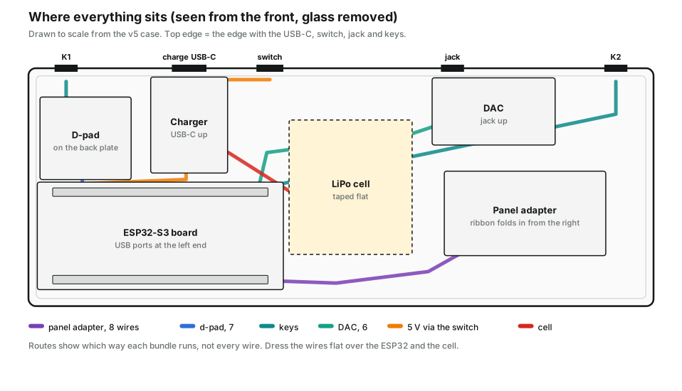
- Charge board. In the power bay, butted up against the ESP32, its USB-C socket through the slot in the top edge. Its four lights are bright and can show through the glass; a piece of dark tape over them fixes that.
- Switch. In its pocket in the top edge, lever toward the wall.
- Cell. 400 mAh, size 403035 (4 x 30 x 35 mm), taped flat in the middle of the case, away from the screw posts.
- Runtime. About 3.5 hours of on time from a full charge. The switch is the only off, so switch it off when you put it down.
- Charging. Charge through the charge board's USB-C in the top edge. The ESP32's own ports are for flashing, with the switch off.
Add-on: headphones
Why. The ESP32-S3 has no proper audio output of its own. A small DAC board turns its digital audio into a headphone signal. The sequencer (coming soon) needs it.
Parts, the solder bridges (the labels can be printed backwards), wiring, the Sound test and troubleshooting are on the module page.
On the speed reader
- Pins. VIN to 3V3, GND to GND, LCK to GPIO 4, DIN to GPIO 5, BCK to GPIO 6, and the DAC's SCK pin to GND. Also in the pin map.
- In the case. The DAC sits next to the panel adapter at the right end, with the jack mouth facing the top wall, and the jack comes out through a hole in the top edge.
- The jack hole. The wall around it is 2 mm thick with a counterbore, so plugs with a body up to 9 mm across seat fully. Push the plug all the way home: a half-inserted plug plays in one ear only.
- Test. Pick Sound test under WiFi and settings: a sweep in both ears, then left, then right. No reflash needed.
Case
The case is a front shell, a back plate and a small ring around the d-pad stick. Closed, it is 162.6 x 62 x 13.8 mm, plus the 2.5 mm ring on the back. The glass slides in from the open right end and the back plate's end wall closes it.
Get the case files by email
The print files for this case are not in the repo; they come by email. Leave your address and I will send them, along with case updates and new firmware.
Watch the case layout walkthrough
- Front shell, printed face down as the file comes. Use 5 perimeters so the 2 mm walls are solid, at 0.2 mm layers. It needs supports only under the six screw posts and their webs, and the small shelf at the top right. Clean the glass slot well afterwards: the glass slides through it.
- Back plate, printed outside face down. No supports. The two parts print as separate objects, so each can take its own filament: mine is a black front and a clear back.
- D-pad ring, ring down, spigot up. Not on the main plate; print it on its own.
- Clear PETG. For the clearest look, print at 100 % infill so every part is solid plastic. The support marks show through; I live with that.
Assemble
- Glass. Slide the glass in from the open right end, display side up, ribbon trailing, until it meets the left wall. Do not force it. It sits in a close slot with no padding; if it rattles once the case is closed, put a layer of tape on the tops of the screw posts under it.
- Ribbon and adapter. Fold the ribbon 180 degrees back into the adapter's socket without creasing it, and tape the adapter down. Where it lands depends on the ribbon's length.
- Keys. One in the pocket at each end of the top wall, button out, hot glued from the inside. Wire each one on its own.
- Power switch (battery add-on) into its pocket, lever toward the wall.
- Board and d-pad. The ESP32 goes on the back plate's rails, USB end at the left, held by the stop at its far end. The d-pad module goes upside down onto its four pegs, with its UP label toward the bottom edge.
- Add-ons. Charge board in the power bay with its USB-C on the slot, cell taped flat, DAC with its jack in the top wall hole. Wire everything, then dress the wires flat.
- Close it. Hook the back plate's two left tabs into the left wall, lower it so its end wall closes the right end, and drive in the six M2 x 5 screws. Snug, not tight.
- D-pad ring. Push the ring's spigot into the stick hole on the back and glue it.
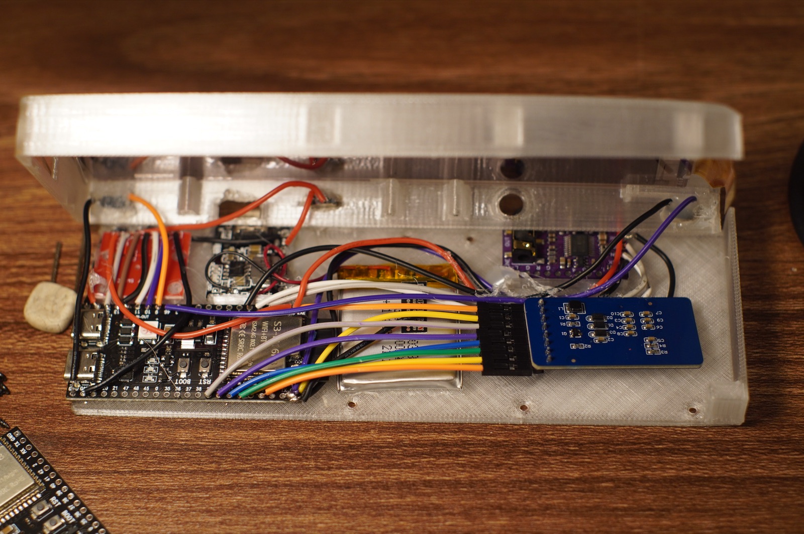
CheckYou should see the reader start up with the case closed, every d-pad direction and key answering in Button test, and no part rattling when you shake it gently.
Using it
Speed read
In the menu, pick Books, then Speed reading. Its options come up first: Start (the book you have open), Book (to pick another), Words, Speed and Mode. Press center on Start to begin. It starts from the page you are on and keeps your place in step with the page view, so you can switch between the two. Sentence ends hold a little longer than other words, and commas a little longer again, which makes it read like speech instead of a metronome. The screen shows the speed, the page and the time left in the book at your speed.
| Press | While it plays | While paused |
|---|---|---|
| Up, down | Speed, 25 words a minute a press | Speed |
| Right | Words per flash: 1, 2, 3 | Words per flash |
| Center | Pause | Play |
| Right shoulder key | Hold to read, let go to pause | |
| Left shoulder key | Back 20 words | Back 20 words |
| Center twice, quickly | Back to the page | Back to the page |
Left on the d-pad does nothing in speed read. Speed and words per flash are remembered. Resume in the main menu takes you back to whichever you used last, speed read or the page view.
Speed read has two modes, under Mode in its settings. Normal is the default and uses Good Display's own waveform for the panel: it tops out around 120 words a minute at one word a flash, so roughly 240 at two and 360 at three. Turbo (the tile reads "Turbo, more wear") drives the panel with a faster custom waveform, up to about 300, 600 and 900, with darker blacks and almost no ghosting. It wears the panel harder, so use Normal for long sessions. If you set a speed the panel cannot keep up with, the top line shows REAL and the pace it is actually managing. I read at two words.
Every so often, at a sentence end, the reader does one full refresh (the black and white flash) to wipe away faint ghosts of earlier words. Turbo does it more often, but mostly as a quick black and white blink (under half a second) instead of the slower full refresh. Pausing does not refresh the screen; in Turbo the same quick blink runs when you start again, so the first words come up clean.
Look after the screen
E Ink panels are tough in daily use, but a few habits keep this one healthy. The firmware handles most of it; these are the parts that are up to you.
- Ghosts that will not clear. A faint ghost of earlier words is normal and the next full refresh wipes it. If a ghost in the word area survives a full refresh, switch to Normal or slow down. That is the early sign of burn-in, and the panel recovers if you back off.
- Turbo is the wear setting. Normal uses the panel maker's own waveform and is fine for hours. Turbo trades panel life for speed, so save it for showing off or short bursts.
- Pause before you switch off. Cutting power in the middle of a refresh (the battery switch, or pulling the cable) can leave a streaky, half-drawn picture. It does no damage and the next full refresh fixes it, but pausing first avoids it.
- Leaving it on a page is fine. E Ink holds its picture with no power, and the reader switches the panel's high voltage off after every refresh, so a page or a paused frame can stay on the glass for days. Before you put it away for months, open a page of plain text, so no one image sits on the glass that long.
- Heat, cold and sun. Good Display rates this panel for 0 to 50 C (store it between -25 and 70 C). Cold makes words greyer and refreshes slower; a closed car in summer can go past the top of that range. Reading in sunlight is fine, but do not store it on a sunny windowsill or dashboard: long UV and heat age any E Ink panel.
- The glass itself. It is thin and long, and it cracks if it bends. Never press on its middle, and never post the reader without the case closed.
Books and pages
In the page view, right or the left shoulder key turns to the next page, and left or the right shoulder key goes back one. Up and down also go back. Center opens the menu, and Books, then Normal reading, lists your books with Text size and Jump to page. Upload plain text books from Books and games (WiFi), under WiFi and settings, and the reader lays out the pages itself. For PDF books, the repo has a converter (tools/pdf2book.py) that keeps figures and layout better. If the picture is upside down, pick Flip screen under WiFi and settings.
Sequencer (coming soon)
A 4 track sequencer for chopping up samples and programming patterns on the e-ink grid, with sound through the headphones add-on. It is a separate firmware for this same build, and it comes out a few days after this guide. Leave your email at the top of the page and I will tell you the day it is out.
Troubleshooting
The board does not show up when I try to flash it.
The screen stays blank after flashing.
There are no books, and nowhere to upload them.
pio run -e esp32s3_579_fast -t uploadfs. Only do it the first time; it wipes the books on every later run.One press shows up as a different button, or as two.
A button reads as held down all the time.
include/pins.h.It will not start while I hold a key.
Headphones play in one ear only.
The DAC makes no sound at all.
It restarts when I unplug the charger.
Faint traces of earlier words stay on the screen.
The ribbon will not fold into the adapter without creasing.
The panel cracked.
Still stuck? Post in #speed-reader on the Discord with a photo of your wiring and what Button test shows.
Going further: the max build
The max build keeps everything here and adds an Orange Pi Zero 3W with 4 GB of memory: a small Linux computer, 65 x 32 mm, with WiFi 6 and Bluetooth. The ESP32 stays in charge of the screen, the buttons and sleep, and switches the Orange Pi on only when it is needed, because Linux cannot sleep the way the ESP32 does and draws 2 to 3 W just idling.
With it come a microphone for voice, a small vibration motor, a 256 GB microSD card, and Bluetooth headphones. The ideas I want to try on it: offline Wikipedia answers streamed at speed read pace, talking to a coding agent from the reader, and a dedicated pad and knob box that turns the sequencer into a pocket studio. The parts come to about $145, half of it the Linux board. It is a build guide only, no kit, and it is next on my bench.
Get the max build when it is ready
Leave your email and I will send you the max build guide the day it goes up.
Help and community
Stuck, or built one and want to show it off? Ask in #ereader on the _stition Discord; the speed reader shares that room with the other e-reader builds for now. Other builders answer questions too, and I drop in regularly. For bugs in the firmware, open an issue on GitHub (ereader issues). If this guide helped you, buy me a coffee on Ko-fi. Pictures of your build are the best contribution of all.
Rather skip the parts hunt and the fine soldering? A kit is coming: every part matched to the firmware, a printed case, and a board that arrives flashed and boot-tested, in one box. Sign up and you will hear the day it opens.
Updates on this build and what comes next
I am still adding to this reader (the sequencer, microSD, a faster panel driver) and building the max version. Get an email when something ships.
Open source. Firmware under the Apache License 2.0, case files under CERN-OHL-P v2, and this guide under CC BY 4.0. Copy it, change it, build one for a friend; just credit the original. Firmware: github.com/AllanBinder/ereader. Good Display sponsors this guide and supplied the panels I built mine with.