What it adds
The ESP32-S3 has no proper audio output of its own. A small DAC board turns its digital audio into a clean headphone signal, and this one has the 3.5 mm jack already on it.
The board is a purple PCM5102A (sold as GY-PCM5102). It talks to the ESP32 over I2S: three signal wires, plus power. In the reader firmware it plays the Sound test for now; on the speed reader it is also what the upcoming sequencer plays through (a separate firmware, see that guide).
This is a _stition expansion module: one add-on that fits several of my builds. Your build's own guide says where it sits in that case; this page is the how-to. Everything here is free and open source. Questions? Ask on the _stition Discord.
Works with
- Speed reader min (wide 5.79 in). Supported. Pins in the pin table, case position in the speed reader guide.
- WiFi e-reader (5.76 in). Coming. Needs pins and firmware support.
- Solar e-reader. Coming.
Parts
| Part | What to buy | Price | Notes |
|---|---|---|---|
| DAC | PCM5102A DAC board with a 3.5 mm jack (the purple GY-PCM5102) | About $12 for 2 | Six header pins: VIN, GND, LCK, DIN, BCK, SCK. |
| Headphones | Any wired headphones with a 3.5 mm plug | $0 if you have some | Check how big a plug your build's case takes (the speed reader takes plugs up to 9 mm across). |
Some links are affiliate links: if you buy through them, the shop pays me a small cut at no extra cost to you. It funds the next guide.
Wiring
In the board's header order:
- VIN to 3V3. Not 5V: on these dev boards the 5V pin is an input, so it is not a reliable supply.
- GND to any GND pin.
- LCK (word select, left or right) to the host's I2S word select pin.
- DIN (audio data) to the host's I2S data pin.
- BCK (bit clock) to the host's I2S bit clock pin.
- SCK to GND. It is not a board pin. Tied to ground, it tells the DAC to make its own clock from BCK, which saves a wire.
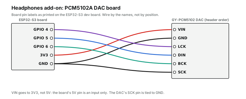
Pins for your build
| Module pin | Speed reader min (wide 5.79 in) | WiFi e-reader (5.76 in) | Solar e-reader |
|---|---|---|---|
| VIN | 3V3 | coming | coming |
| GND | GND | coming | coming |
| LCK | GPIO 4 | coming | coming |
| DIN | GPIO 5 | coming | coming |
| BCK | GPIO 6 | coming | coming |
| SCK | GND | coming | coming |
The numbers are the GPIO numbers printed next to the board's pins. Each build's include/pins.h in the firmware is the source of truth if this table and the code ever disagree.
Steps
Set the solder bridges
On the back of the board are four small solder bridge pads, numbered 1 to 4, each with an H and an L side. The usual setting is 1 L, 2 L, 3 H, 4 L. Check the silkscreen before you trust it: on mine the H and L labels were printed the wrong way round (the pad marked H was really ground). So meter each side to GND first: the L side is the one that beeps to GND.
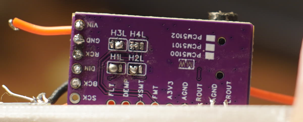
CheckYou should see each of the four bridges joined to exactly one side, with no blob touching both.
Wire it
Six wires in header order, per the wiring and your build's column in the pin table. SCK goes to GND, not to a board pin.
CheckYou should hear the multimeter beep between SCK and GND, and between each of LCK, DIN and BCK and its board pin.
Fit the jack in the case
Line the jack's mouth up with the hole in your build's case and fix the board so a plug pushed in does not shove it back. Your build's guide says where it goes.
CheckYou should be able to push a plug all the way home with the case closed, and feel it click.
Check it works
Plug in your headphones, all the way home, and pick Sound test under WiFi and settings in the reader's menu. It plays a tone sweep in both ears, then the left ear only, then the right ear only. No reflash needed.
CheckYou should hear the sweep in both ears, then the left ear alone, then the right ear alone. Left only all the way through means the plug is not fully in.
No Sound test in your menu? Builds whose firmware does not have it yet can use the tone test from the repo instead. On the speed reader, with PlatformIO:
pio run -e dac_tone -t uploadIt replaces the reader firmware with a test that plays the same sweep. Flash the reader back afterwards with the upload command from your build's guide.
Troubleshooting
Headphones play in one ear only.
The DAC makes no sound at all.
The sound is distorted or very loud.
There is no Sound test in my menu.
dac_tone test above.Still stuck? Post in #ereader on the Discord with a photo of your wiring and which build it is in.
Open source. Firmware under the Apache License 2.0 at github.com/AllanBinder/ereader, and this page under CC BY 4.0. Copy it, change it; just credit the original.