What it adds
Without a battery the reader runs from a USB cable. E Ink keeps its picture with no power and the reader saves your place, so a USB-only reader is fine on a desk. The battery is what makes it a pocket reader.
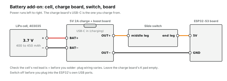
A small rechargeable pouch cell sits flat inside the case. A charge and boost board fills it from its own USB-C socket and turns the cell's 3.7 V into a steady 5 V, which goes into the ESP32's 5V pin just like USB would. A slide switch in that line cuts all power, so nothing can drain the cell in a bag. I tried another power bank board first and three of them shut off the moment the screen refreshed; this one holds.
The switch is the only on and off. Flip it on and the reader boots, flip it off and everything stops. There is no sleep or auto-off in this version, so switch it off when you put it down.
This is a _stition expansion module: one add-on that fits several of my builds. Your build's own guide says where it sits in that case; this page is the how-to. Everything here is free and open source. Questions? Ask on the _stition Discord.
Works with
- Speed reader min (wide 5.79 in). Supported. Wiring in the pin table, case position in the speed reader guide.
- WiFi e-reader (5.76 in). Coming. The wiring is the same idea; the case position is not worked out yet.
- Solar e-reader. Coming.
This module needs no firmware support at all: to the board it looks exactly like a USB cable. Any ESP32-S3 dev board with a 5V pin can use it.
Parts
| Part | What to buy | Price | Notes |
|---|---|---|---|
| Charger | Type-C 5V 2A charge and boost board, "USB not welded", also sold as an "18650 power bank module, 5V 2A, Type-C". Buy the version with no USB-A socket fitted. | About $10 for 6 | About 20 x 25 mm, USB-C in the middle of one edge. Avoid "5V 3.1A" (IP5310) boards: they dropped my reader on battery. Charges the cell from USB and boosts it to a steady 5 V for the board. One part does both jobs. |
| Cell | LiPo pouch cell, 403035 size, 400 to 450 mAh, with its protection board built in | About $10 | Size 403035: 4 x 30 x 35 mm. Mine is 400 mAh with two bare wires; the Amazon one is 450 mAh with a small JST plug. Cut the plug off and check which lead is red (+) before you solder; plug wiring varies. |
| Switch | MSK-12C02 SMD slide switch, 7 x 3 mm body | About $7 for 50 | Cuts all power. Your build's case has a pocket for it. |
No battery ships with any kit: lithium cells are hard to ship across borders and easy to buy locally. Some links are affiliate links: if you buy through them, the shop pays me a small cut at no extra cost to you. It funds the next guide.
Runtime. A 400 mAh cell runs my speed reader for about 3.5 hours of on time from a full charge. The switch is the only off, so keep the habit of switching it off; a bigger cell runs longer if your case has room for it.
LiPo safety basics
- Never puncture, bend or crush the cell. A damaged pouch cell can catch fire. Keep it away from screw tips and sharp print edges, and replace any cell that has puffed up.
- Never let the two cell wires touch. Cut and strip one wire at a time, and tape the end you are not working on.
- Use a protected cell, one with its small protection board built in, and a charge board made for single lithium cells.
- Check the polarity before you solder: red is +, black is −, and the charge board's pads are labeled. Backwards can destroy the charger and damage the cell. (I did it for a minute by accident; the cell's protection saved mine. Do not count on that.)
- Stay close the first time it charges. Charge on a hard surface, away from anything that burns, and unplug it if the cell gets more than warm.
- Do not power the board two ways at once. The charger feeds the board's 5V pin, so never plug into the ESP32's own USB ports with the battery switch on: it pushes current back into the charger. Switch off first, then plug in to flash.
Wiring
The charge board has three groups of pads: BAT + / − on one edge for the cell, + 5V − on another for the output, and a small K pad (the "key") in a corner.
- Cell red to BAT +, cell black to BAT −.
- Output + to one end of the slide switch, the switch's middle leg to the ESP32's 5V pin.
- Output − to any GND pin on the ESP32.
- K stays empty. The board wakes by itself when the switch closes, so K is not needed.
Pins for your build
| Module pad | Speed reader min (wide 5.79 in) | WiFi e-reader (5.76 in) | Solar e-reader |
|---|---|---|---|
| Output + | Slide switch, then the 5V pin | coming | coming |
| Output − | GND | coming | coming |
| BAT + / − | Cell red / black | coming | coming |
| K | nothing | coming | coming |
The board's 5V pin is labeled 5V or 5Vin, next to GND. Any GND pin will do.
Steps
Test the charge board on its own
Solder the cell to BAT, red to +, one wire at a time. Plug a USB-C cable into the charge board (not the ESP32) and watch its four lights.
CheckYou should see the four lights chase, with the last one blinking while it charges. All four solid means the cell is full.
Seat the switch and the board
Put the slide switch in its pocket and the charge board in its spot, with the board's USB-C socket lined up with the slot in the case. Your build's guide says where both go.
CheckYou should be able to plug a USB-C cable into the charge board through the case, and reach the switch lever from outside.
Wire the output
Output + to the switch, the switch to the ESP32's 5V pin, output − to GND. Unplug every USB cable first.
CheckYou should read about 5.0 V between the 5V pin and GND in DC volts with the switch on, and nothing with it off. Do not use the continuity beep here: it beeps across a live cell and across 5V and GND (the board's capacitors) even when nothing is wrong.
Fix the cell in place
Tape the cell flat, away from screw posts and sharp edges, with its wires lying loose rather than pulled tight.
CheckYou should see no screw tip or print edge touching the cell when the case is closed.
Check it works
Unplug every cable and flip the switch on. Open a book and turn a few pages, then let the reader do a full refresh (the black and white flash).
CheckYou should see the reader boot with no cable plugged in, and the screen refresh without it shutting off. With the switch off, a USB cable in the charge board shows the chasing lights.
Troubleshooting
It restarts when I unplug the charger.
Nothing happens when I flip the switch.
The reader shuts off when the screen refreshes.
The lights do not chase when I plug in USB.
The board will not flash with the battery in.
The charger's lights show through the screen.
Still stuck? Post in #ereader on the Discord with a photo of your wiring and which build it is in.
Open source. Firmware under the Apache License 2.0 at github.com/AllanBinder/ereader, and this page under CC BY 4.0. Copy it, change it; just credit the original.